http://www.crecorder.com/techInfo/commuProtocols.jsp
|
COMMUNICATION PROTOCOLS
A “communication protocol” is a means by which data is exchanged between the vehicle’s on-board computer and an external data retrieval device, such as a Code Reader or Scan Tool. The SAE has defined three distinct communication protocol “classifications,” based on the speed at which data transfer takes place:
Currently, five communication protocols are defined for use in OBD2 computer control systems. An OBD2-compliant vehicle will employ one of the following protocols:
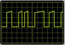
ISO 9141-2 Classification: A Commonly Used On: European, Asian, and some Chrysler Description: The ISO 9141-2 protocol is essentially a serial interface, similar to the RS232 interface found in personal computers. The ISO 9141-2 data bus can be implemented as either a single-wire or two-wire interface (DLC pins 7 and 15) with a data transfer speed of up to 10.4 Kb/s. The “K” line (pin 7) is a bidirectional line. During initialization, this line carries address information or (in the case of fast initialization), the “wake up” pattern from the Code Reader or Scan Tool to the vehicle’s computer. After initialization, bidirectional data flow between the Code Reader or Scan Tool and the vehicle’s computer takes place over the “K” line. The “L” line (pin 15) is a unidirectional line (from the Code Reader or Scan Tool to the vehicle’s computer). It is used only during initialization to carry address information or (in the case of fast initialization), the “wake up” pattern from the Code Reader or Scan Tool to the vehicle’s computer simultaneously with the “K” line. After initialization, the “L” line is held in a “high” (logic “1”) state. The ISO 9141-2 data signal is a square wave of uniform frequency, with a varying voltage level (either +12VDC or 0VDC), as illustrated.
ISO 14230-4 KW 2000 Classification: A Commonly Used On: European, Asian, and some Chrysler Description: The ISO 14230-4 KW 2000 protocol is a variation of the ISO 9141-2 protocol, complying with the specific requirements of ISO 14230-2 and ISO 14230 Parts 2 and 3. The ISO ISO 14230-4 data bus can be implemented as either a single-wire or two-wire interface (DLC pins 7 and 15) with a data transfer speed of up to 10.4 Kb/s. The “K” line (pin 7) is a bidirectional line. During initialization, this line carries address information or (in the case of fast initialization), the “wake up” pattern from the Code Reader or Scan Tool to the vehicle’s computer. After initialization, bidirectional data flow between the Code Reader or Scan Tool and the vehicle’s computer takes place over the “K” line. The “L” line (pin 15) is a unidirectional line (from the Code Reader or Scan Tool to the vehicle’s computer). It is used only during initialization to carry address information or (in the case of fast initialization), the “wake up” pattern from the Code Reader or Scan Tool to the vehicle’s computer simultaneously with the “K” line. After initialization, the “L” line is held in a “high” (logic “1”) state. The ISO 14230-4 KW 2000 data signal is a square wave of uniform frequency, with a varying voltage level (either +12VDC or 0VDC), as illustrated.
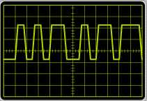
SAE J1850 (VPW 10.4K) Classification: B Commonly Used On: Chrysler and General Motors Description: The SAE J1850 (VPW 10.4K) data bus is implemented as a single-wire bidirectional interface (DLC pin 2), with a data transfer speed of 10.4 Kb/s. The data signal is a series of pulses of uniform amplitude (7VDC) and variable pulse width (VPW), as illustrated.
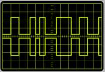
SAE J1850 (PWM 41.6K) Classification: B Commonly Used On: Ford Description: The SAE J1850 (PWM 41.6K) protocol is implemented as a two-wire bidirectional interface (DLC pins 2 and 10) that supports data transfer rates of up to 41.6 Kb/s. The “+” (pin 2) and “-“ (pin 10) bus lines carry differential signals; that is, the signal on the “-“ line is an exact inversion of the signal on the “+” line. This implementation minimizes the effects of Radio Frequency Interference (RFI) or Electromagnetic Interference (EMI) on the data signal. The SAE J1850 (PWM 41.6K) data signal is a series of differential pulses of uniform amplitude (+5VDC, -5VDC) and modulated pulse width (PWM), as illustrated.
ISO 15765 CAN (Control Area Network) Classification: C Commonly Used On: Beginning in 2008, all new vehicles will be required to use the CAN protocol Description: The ISO 15765 CAN protocol is implemented as a two-wire bidirectional interface (DLC pins 6 and 14) that supports data transfer rates of up to 1 Mb/s. The “High” (pin 6) and “Low“ (pin 14) bus lines carry differential signals; that is, the signal on the “Low“ line is an exact inversion of the signal on the “High” line. This implementation minimizes the effects of Radio Frequency Interference (RFI) or Electromagnetic Interference (EMI) on the data signal. The ISO 15765 CAN data signal is a series of differential pulses of uniform amplitude (+5VDC, -5VDC) and modulated pulse width (PWM), as illustrated.
|
Vehicle’s communication protocol,布布扣,bubuko.com
Vehicle’s communication protocol
原文:http://www.cnblogs.com/shangdawei/p/3570770.html