1 Transceiver Design
As we look into the schematics of the GSI transceiver reference design, the filter in the transmission path will be as the Fig.1 shows:
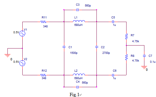
If we focus on the filter and note that the input signal applied are differential in a complementary (push-pull or balanced) manner,
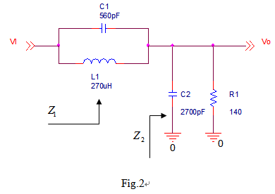
the half-circuit analysis can be applied and the circuit in Fig.2 is what we can get from the simplification of Fig.1.
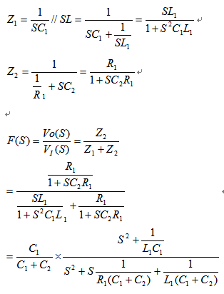
From Fig,2, the following relations can be achieved as follows:
If we define W n as the resonance frequency and W o as the 3dB frequency, we can get the following relations:
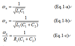
We can see from the above equations that the inductor and the capacitor decide the resonance frequency.

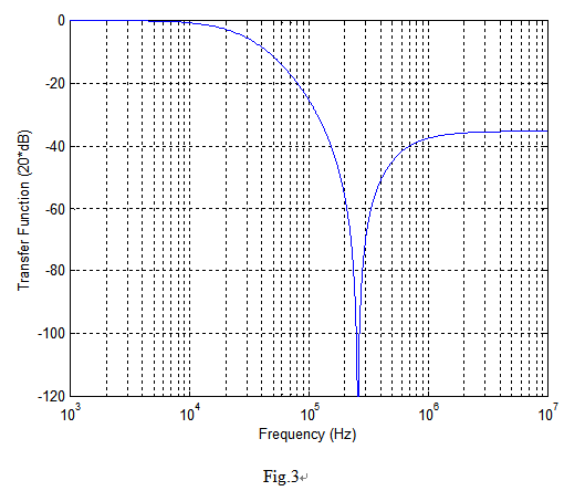
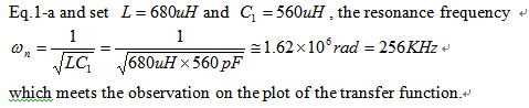
As we investigate the plot of the transfer function, we can see that there is a notch in the frequency about 250~300KHz. If we calculate the resonance frequency using
The filter is a second-order LCR resonator by itself and its configure is a low-pass filter. The parallel resonance circuit (the shunt circuit of capacitor and inductor) is
used to obtain a pair of transmission zeros on the -axis. These two zeros will introduce a drop around the resonance frequency and makes the slope of the transfer
function sharper.
原文:https://www.cnblogs.com/huangbaobaoi/p/10326753.html